graphViz: Как использовать фиксированные позиции для узлов из «аккуратного» макета, но иметь довольно изогнутые края из «точечного» макета?
У меня есть этот точечный код, который я использую в RdiagrammeR-упаковка:
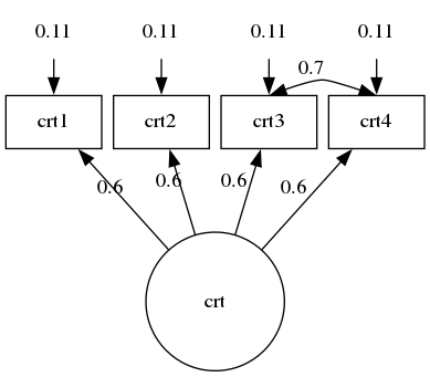
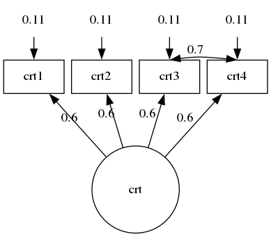
      grViz("digraph {

  graph [layout = neato,
  overlap = false,
  outputorder = edgesfirst]

  node [shape = rectangle]

# Error Certainty
crt1e[pos = '11.1,  15!',  label = '0.11', width = 0.9, shape = none]
crt2e[pos = '12.3,  15!',  label = '0.11', width = 0.9, shape = none]
crt3e[pos = '13.5,  15!',  label = '0.11', width = 0.9, shape = none]
crt4e[pos = '14.7,  15!',  label = '0.11', width = 0.9, shape = none]

# Certainty
crt1 [pos = '11.1,  14!',  label = 'crt1', width = 0.9]
crt2 [pos = '12.3,  14!',  label = 'crt2', width = 0.9]
crt3 [pos = '13.5,  14!',  label = 'crt3', width = 0.9]
crt4 [pos = '14.7,  14!',  label = 'crt4', width = 0.9]

# Latent Certainty
crt  [pos = '12.9,  12!',  label = 'crt',  width = 1.3, shape = circle]

# Path Certainty
crt->crt1 [label = '0.6']
crt->crt2 [label = '0.6']
crt->crt3 [label = '0.6']
crt->crt4 [label = '0.6']

# Covariance
crt3:n->crt4:n[label = '0.7', dir = both, constraint = false]

# Error Path
crt1e->crt1
crt2e->crt2
crt3e->crt3
crt4e->crt4
}")
Это выглядит именно так, как я хочу, за исключением границы между crt3 и crt4. Я хочу, чтобы этот край был изогнут вверх. Мне также нужно вручную контролировать положение каждого узла. Как я могу достичь обоих одновременно?
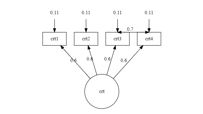
Я попытался использовать «точечную» раскладку. Это создает красиво изогнутый край crt3->crt4, но не поддерживает фиксированные положения.
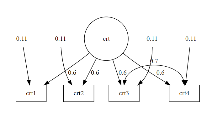
Добавление фиктивного узла между crt3 и crt4 и использование splines = true испортили расстояния между всеми узлами на моей диаграмме.
РЕДАКТИРОВАТЬ
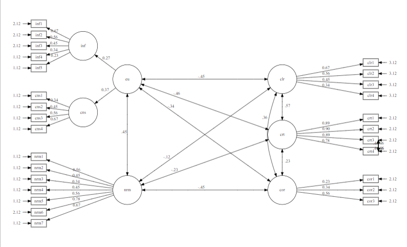
Я попробовал предложенное решение в более широком контексте. Здесь края рисуются друг над другом, а не расходятся.
      grViz("digraph SEM{

graph [layout = neato,
outputorder = edgesfirst,
# overlap = false,
splines = true]

node [shape = rectangle, width = 0.7, height = 0.3]

# Nodes
eu   [pos = '-1,  5!',  width = 1.3, shape = circle]
nrm  [pos = '-1,  0!', width = 1.3, shape = circle]
inf  [pos = '-3, 6.5!', width = 1.3, shape = circle]
cns  [pos = '-3, 3.5!', width = 1.3, shape = circle]

clr  [pos = '6, 5!', width = 1.3, shape = circle]
crt  [pos = '6, 2.5!', width = 1.3, shape = circle]
cor  [pos = '6, 0!', width = 1.3, shape = circle]

inf1 [pos = '-5, 7.5!']
inf2 [pos = '-5, 7!']
inf3 [pos = '-5, 6.5!']
inf4 [pos = '-5, 6!']
inf5 [pos = '-5, 5.5!']

cns1 [pos = '-5, 4.25!']
cns2 [pos = '-5, 3.75!']
cns3 [pos = '-5, 3.25!']
cns4 [pos = '-5, 2.75!']

nrm1 [pos = '-5, 1.5!']
nrm2 [pos = '-5, 1!']
nrm3 [pos = '-5, 0.5!']
nrm4 [pos = '-5, 0!']
nrm5 [pos = '-5, -0.5!']
nrm6 [pos = '-5, -1!']
nrm7 [pos = '-5, -1.5!']

clr1 [pos = '10, 5.75!']
clr2 [pos = '10, 5.25!']
clr3 [pos = '10, 4.75!']
clr4 [pos = '10, 4.25!']

crt1 [pos = '10, 3.25!']
crt2 [pos = '10, 2.75!']
crt3 [pos = '10, 2.25!']
crt4 [pos = '10, 1.75!']

cor1 [pos = '10, 0.5!']
cor2 [pos = '10, 0!']
cor3 [pos = '10, -0.5!']

inf1e[pos = '-6, 7.5!', shape = none, label = '2.12', width = 0.05]
inf2e[pos = '-6, 7!', shape = none, label = '2.12', width = 0.05]
inf3e[pos = '-6, 6.5!', shape = none, label = '2.12', width = 0.05]
inf4e[pos = '-6, 6!', shape = none, label = '1.12', width = 0.05]
inf5e[pos = '-6, 5.5!', shape = none, label = '1.12', width = 0.05]

cns1e[pos = '-6, 4.25!', shape = none, label = '1.12', width = 0.05]
cns2e[pos = '-6, 3.75!', shape = none, label = '1.12', width = 0.05]
cns3e[pos = '-6, 3.25!', shape = none, label = '1.12', width = 0.05]
cns4e[pos = '-6, 2.75!', shape = none, label = '1.12', width = 0.05]

nrm1e[pos = '-6, 1.5!', shape = none, label = '1.12', width = 0.05]
nrm2e[pos = '-6, 1!', shape = none, label = '1.12', width = 0.05]
nrm3e[pos = '-6, 0.5!', shape = none, label = '1.12', width = 0.05]
nrm4e[pos = '-6, 0!', shape = none, label = '1.12', width = 0.05]
nrm5e[pos = '-6, -0.5!', shape = none, label = '1.12', width = 0.05]
nrm6e[pos = '-6, -1!', shape = none, label = '2.12', width = 0.05]
nrm7e[pos = '-6, -1.5!', shape = none, label = '1.12', width = 0.05]

clr1e[pos = '11, 5.75!', shape = none, label = '3.12', width = 0.05]
clr2e[pos = '11, 5.25!', shape = none, label = '3.12', width = 0.05]
clr3e[pos = '11, 4.75!', shape = none, label = '3.12', width = 0.05]
clr4e[pos = '11, 4.25!', shape = none, label = '3.12', width = 0.05]

crt1e[pos = '11, 3.25!', shape = none, label = '2.12', width = 0.05]
crt2e[pos = '11, 2.75!', shape = none, label = '2.12', width = 0.05]
crt3e[pos = '11, 2.25!', shape = none, label = '2.12', width = 0.05]
crt4e[pos = '11, 1.75!', shape = none, label = '2.12', width = 0.05]

cor1e[pos = '11, 0.5!', shape = none, label = '2.12', width = 0.05]
cor2e[pos = '11, 0!', shape = none, label = '2.12', width = 0.05]
cor3e[pos = '11, -0.5!', shape = none, label = '2.12', width = 0.05]

# Edges
eu->inf [taillabel = '0.27', labeldistance = 5, labelangle = -15]
eu->cns [taillabel = '0.37', labeldistance = 3.5, labelangle = -25]

inf->inf1 [label = '0.67']
inf->inf2 [label = '0.56']
inf->inf3 [label = '0.45']
inf->inf4 [label = '0.34']
inf->inf5 [label = '0.23']

cns->cns1 [label = '0.34']
cns->cns2 [label = '0.45']
cns->cns3 [label = '0.56']
cns->cns4 [label = '0.67']

nrm->nrm1 [label = '0.56']
nrm->nrm2 [label = '0.45']
nrm->nrm3 [label = '0.34']
nrm->nrm4 [label = '0.45']
nrm->nrm5 [label = '0.56']
nrm->nrm6 [label = '0.78']
nrm->nrm7 [label = '0.67']

crt->crt1 [label = '0.89']
crt->crt2 [label = '0.90']
crt->crt3 [label = '0.89']
crt->crt4 [label = '0.78']

clr->clr1 [label = '0.67']
clr->clr2 [label = '0.56']
clr->clr3 [label = '0.45']
clr->clr4 [label = '0.34']

cor->cor1 [label = '0.23']
cor->cor2 [label = '0.34']
cor->cor3 [label = '0.56']

eu->nrm [dir = both, label = '.45 ']
eu->clr [dir = both, label = '-.45']
eu->crt [dir = both, taillabel = '-.46', labeldistance = 12, labelangle = 5]
eu->cor [dir = both, taillabel = '-.34', labeldistance = 12, labelangle = 5]
nrm->crt [dir = both, taillabel = '-.23', labeldistance = 12, labelangle = 5]
nrm->clr [dir = both, taillabel = '-.12', labeldistance = 12, labelangle = 6]
nrm->cor [dir = both, label = '-.45']
crt->clr [dir = both, taillabel = '.57', labeldistance = 5, labelangle = -20]
cor->crt [dir = both, taillabel = '.23', labeldistance = 5, labelangle = -20]
clr->cor [dir = both, taillabel = '.36', labeldistance = 9, labelangle = -5]

inf1e->inf1
inf2e->inf2
inf3e->inf3
inf4e->inf4
inf5e->inf5

cns1e->cns1
cns2e->cns2
cns3e->cns3
cns4e->cns4

nrm1e->nrm1
nrm2e->nrm2
nrm3e->nrm3
nrm4e->nrm4
nrm5e->nrm5
nrm6e->nrm6
nrm7e->nrm7

crt1e->crt1
crt2e->crt2
crt3e->crt3
crt4e->crt4

clr1e->clr1
clr2e->clr2
clr3e->clr3
clr4e->clr4

cor1e->cor1
cor2e->cor2
cor3e->cor3

crt3:e->crt4:e [dir = both, label = '.46']
crt3:e->crt4:e [dir = both, label = '.46']
crt3:e->crt4:e [dir = both, label = '.46']
crt3:e->crt4:e [dir = both, label = '.46']
crt3:e->crt4:e [dir = both, label = '.46']

}")
1 ответ
Если вы добавите splines=true к своим входным данным, вы получите небольшую кривую по краю:
Но если вы добавите 3 (или около того) невидимых мультиребра вот так:
      digraph {

  graph [layout = neato,
  overlap = false,
  outputorder = edgesfirst
  splines=true ///curved  // better than true??
  ]

  node [shape = rectangle]

# Error Certainty
crt1e[pos = "11.1,  15!",  label = "0.11", width = 0.9, shape = none]
crt2e[pos = "12.3,  15!",  label = "0.11", width = 0.9, shape = none]
crt3e[pos = "13.5,  15!",  label = "0.11", width = 0.9, shape = none]
crt4e[pos = "14.7,  15!",  label = "0.11", width = 0.9, shape = none]

# Certainty
crt1 [pos = "11.1,  14!",  label = "crt1", width = 0.9]
crt2 [pos = "12.3,  14!",  label = "crt2", width = 0.9]
crt3 [pos = "13.5,  14!",  label = "crt3", width = 0.9]
crt4 [pos = "14.7,  14!",  label = "crt4", width = 0.9]

# Latent Certainty
crt  [pos = "12.9,  12!",  label = "crt",  width = 1.3, shape = circle]

# Path Certainty
crt->crt1 [label = "0.6"]
crt->crt2 [label = "0.6"]
crt->crt3 [label = "0.6"]
crt->crt4 [label = "0.6"]

# Covariance
crt3:n->crt4:n[label = "", style=invis constraint = false]
crt3:n->crt4:n[label = "", style=invis constraint = false]
crt3:n->crt4:n[label = "", style=invis constraint = false]
crt3:n->crt4:n[label = "0.7", dir = both, constraint = false]

# Error Path
crt1e->crt1
crt2e->crt2
crt3e->crt3
crt4e->crt4
}
Вы получите более выраженную кривую: