Векторизация реального алгоритма обработки координат Kinect для скорости
Недавно я начал работать с Kinect V2 в Linux с pylibfreenect2.
Когда я впервые смог показать данные кадра глубины на диаграмме рассеяния, я был разочарован, увидев, что ни один из пикселей глубины, казалось, не находится в правильном местоположении.
Вид сбоку на комнату (обратите внимание, что потолок изогнут). 
Я провел небольшое исследование и понял, что для конвертации требуется простой триггер.
Для тестирования я начал с предварительно написанной функции в pylibfreenect2, которая принимает столбец, строку и интенсивность пикселя глубины, а затем возвращает фактическое положение этого пикселя:
X, Y, Z = registration.getPointXYZ(undistorted, row, col)
Это делает удивительно хорошую работу по исправлению позиций: 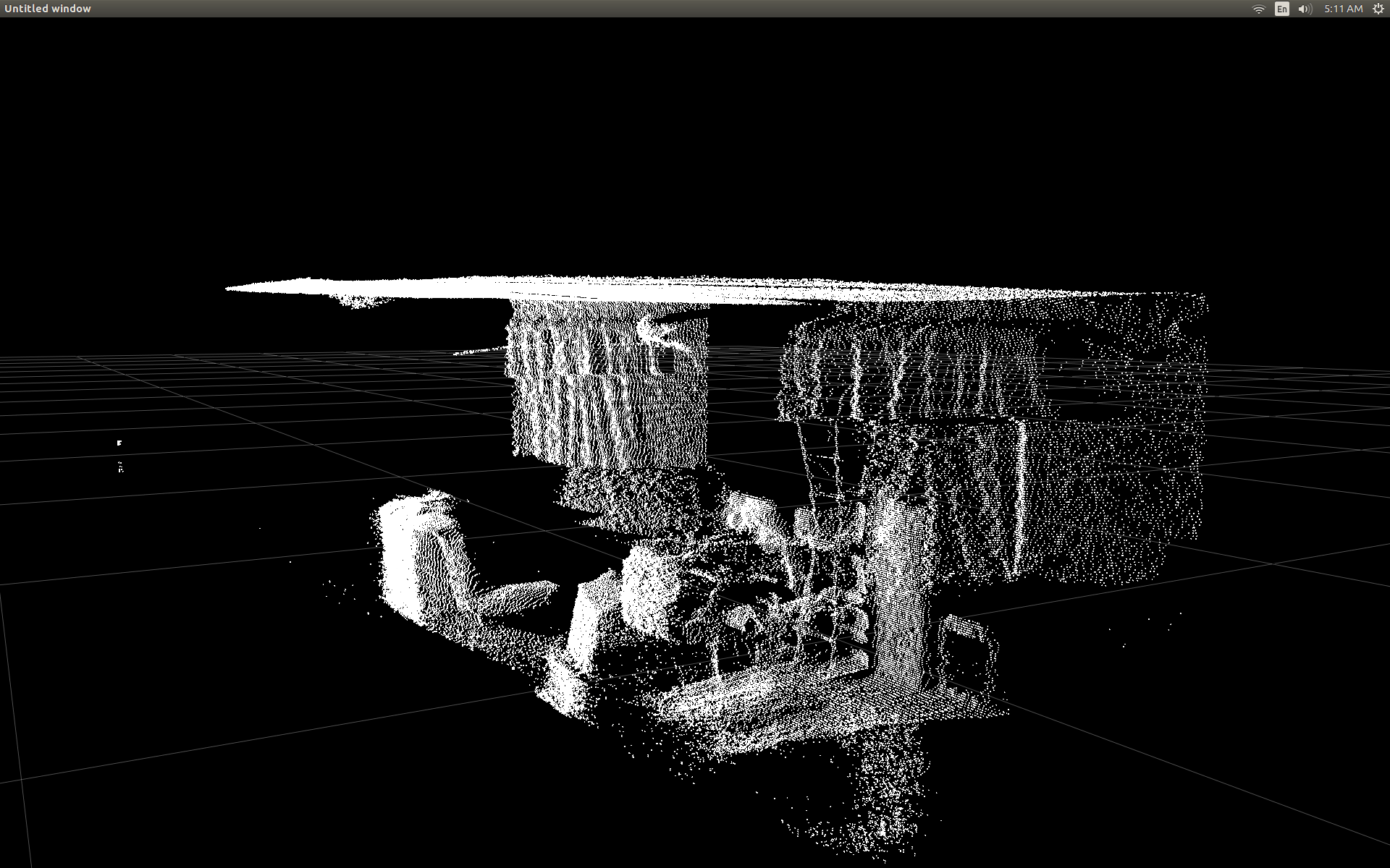
Единственным недостатком использования getPointXYZ() или getPointXYZRGB() является то, что они работают только с одним пикселем за раз. Это может занять некоторое время в Python, поскольку требует использования вложенных циклов for следующим образом:
n_rows = d.shape[0]
n_columns = d.shape[1]
out = np.zeros((n_rows * n_columns, 3), dtype=np.float64)
for row in range(n_rows):
    for col in range(n_columns):
        X, Y, Z = registration.getPointXYZ(undistorted, row, col)
        out[row * n_columns + col] = np.array([Z, X, -Y])
Я попытался лучше понять, как getPointXYZ() вычисляет координату. Насколько мне известно, он выглядит примерно так, как эта функция OpenKinect-для-обработки: deepToPointCloudPos(). Хотя я подозреваю, что версия libfreenect2 имеет больше возможностей.
Используя этот исходный код gitHub в качестве примера, я попытался переписать его на Python для собственных экспериментов и пришел к следующему:
#camera information based on the Kinect v2 hardware
CameraParams = {
  "cx":254.878,
  "cy":205.395,
  "fx":365.456,
  "fy":365.456,
  "k1":0.0905474,
  "k2":-0.26819,
  "k3":0.0950862,
  "p1":0.0,
  "p2":0.0,
}

def depthToPointCloudPos(x_d, y_d, z, scale = 1000):
    #calculate the xyz camera position based on the depth data
    x = (x_d - CameraParams['cx']) * z / CameraParams['fx']
    y = (y_d - CameraParams['cy']) * z / CameraParams['fy']

    return x/scale, y/scale, z/scale
Это сравнение между традиционным getPointXYZ и моей пользовательской функцией: 
Они выглядят очень похожими. Однако с явными различиями. Сравнение слева показывает края, которые являются более прямыми, а также некоторую синусоидальную форму на плоском потолке. Я подозреваю, что это связано с дополнительной математикой.
Мне было бы очень интересно узнать, есть ли у кого-нибудь идеи относительно того, что может отличаться между моей функцией и getPointXYZ из libfreenect2.
Однако главная причина, которую я разместил здесь, это спросить о попытке векторизовать вышеупомянутую функцию для работы над целым массивом, а не циклически проходить через каждый элемент.
Применяя то, что я узнал из вышеизложенного, я смог написать функцию, которая представляется векторизованной альтернативой deepToPointCloudPos:
[РЕДАКТИРОВАТЬ]
Спасибо Бенджамину за помощь в том, чтобы сделать эту функцию еще более эффективной!
def depthMatrixToPointCloudPos(z, scale=1000):
    #bacically this is a vectorized version of depthToPointCloudPos()
    C, R = np.indices(z.shape)

    R = np.subtract(R, CameraParams['cx'])
    R = np.multiply(R, z)
    R = np.divide(R, CameraParams['fx'] * scale)

    C = np.subtract(C, CameraParams['cy'])
    C = np.multiply(C, z)
    C = np.divide(C, CameraParams['fy'] * scale)

    return np.column_stack((z.ravel() / scale, R.ravel(), -C.ravel()))
Это работает и дает те же результаты pointcloud, что и предыдущая функция deepToPointCloudPos(). Единственное отличие состоит в том, что моя скорость обработки данных выросла с ~1 Fps до 5-10 Fps (WhooHoo!). Я считаю, что это устраняет узкое место, вызванное Python, выполняющим все вычисления. Таким образом, мой график рассеяния теперь снова работает гладко с вычисляемыми полуреальными координатами.
Теперь, когда у меня есть эффективная функция для получения трехмерных координат из рамки глубины, я действительно хотел бы применить этот подход также для отображения данных цветных камер на мои пиксели глубины. Однако я не уверен, какие математические или переменные используются для этого, и не было большого упоминания о том, как рассчитать его в Google.
В качестве альтернативы я смог использовать libfreenect2 для сопоставления цветов с пикселями глубины, используя getPointXYZRGB:
#Format undistorted and regisered data to real-world coordinates with mapped colors (dont forget color=out_col in setData)
n_rows = d.shape[0]
n_columns = d.shape[1]
out = np.zeros((n_rows * n_columns, 3), dtype=np.float64)
colors = np.zeros((d.shape[0] * d.shape[1], 3), dtype=np.float64)
for row in range(n_rows):
    for col in range(n_columns):
        X, Y, Z, B, G, R = registration.getPointXYZRGB(undistorted, registered, row, col)
        out[row * n_columns + col] = np.array([X, Y, Z])
        colors[row * n_columns + col] = np.divide([R, G, B], 255)
sp2.setData(pos=np.array(out, dtype=np.float64), color=colors, size=2)
Создает облако точек и цветные вершины (очень медленно <1Fps): 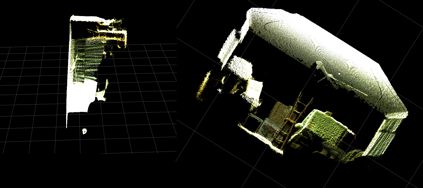
В итоге мои два вопроса в основном:
Какие дополнительные шаги потребуются для того, чтобы реальные данные трехмерных координат, возвращаемые из моей функции deepToPointCloudPos() (и векторизованной реализации), были больше похожи на данные, возвращаемые getPointXYZ() из libfreenect2?
И что может потребоваться для создания (возможно, векторизованного) способа создания карты регистрации глубины цвета в моем собственном приложении?Пожалуйста, смотрите обновление, поскольку это было решено.
[ОБНОВИТЬ]
Мне удалось сопоставить данные цвета для каждого пикселя, используя зарегистрированный кадр. Это было очень просто и требовало только добавления этих строк перед вызовом setData():
colors = registered.asarray(np.uint8)
colors = np.divide(colors, 255)
colors = colors.reshape(colors.shape[0] * colors.shape[1], 4 )
colors = colors[:, :3:] #BGRA to BGR (slices out the alpha channel)
colors = colors[...,::-1] #BGR to RGB
Это позволяет Python быстро обрабатывать данные о цвете и дает плавные результаты. Я обновил / добавил их в функциональный пример ниже.
Реальная обработка координат с регистрацией цвета в реальном времени в Python! 
(Разрешение GIF изображения было значительно уменьшено)
[ОБНОВИТЬ]
Потратив немного больше времени с приложением, я добавил некоторые дополнительные параметры и настроил их значения в надежде улучшить визуальное качество графика рассеяния и, возможно, сделать вещи более понятными для этого примера / вопроса.
Самое главное, я установил непрозрачные вершины:
sp2 = gl.GLScatterPlotItem(pos=pos)
sp2.setGLOptions('opaque') # Ensures not to allow vertexes located behinde other vertexes to be seen.
Затем я заметил, что при масштабировании очень близко к поверхностям расстояние между соседними вершинами будет увеличиваться до тех пор, пока все, что было видно, не будет в основном пустым пространством. Частично это было результатом того, что размер вершин не изменился.
Чтобы помочь в создании "удобного для масштабирования" окна просмотра, полного цветных вершин, я добавил эти строки, которые вычисляют размер точек вершины на основе текущего уровня масштабирования (для каждого обновления):
# Calculate a dynamic vertex size based on window dimensions and camera's position - To become the "size" input for the scatterplot's setData() function.
v_rate = 8.0 # Rate that vertex sizes will increase as zoom level increases (adjust this to any desired value).
v_scale = np.float32(v_rate) / gl_widget.opts['distance'] # Vertex size increases as the camera is "zoomed" towards center of view.
v_offset = (gl_widget.geometry().width() / 1000)**2 # Vertex size is offset based on actual width of the viewport.
v_size = v_scale + v_offset
И о чудо

(Опять же, разрешение изображения GIF было значительно уменьшено)
Может быть, не так хорошо, как снятие шкур с облака точек, но, кажется, это помогает упростить ситуацию, когда вы пытаетесь понять, на что вы на самом деле смотрите.
Все упомянутые модификации были включены в функциональный пример.
[ОБНОВИТЬ]
Как видно из двух предыдущих анимаций, ясно, что облако точек координат реального мира имеет наклонную ориентацию по сравнению с осями сетки. Это потому, что я не компенсировал реальную ориентацию Kinect в реальном слове!
Таким образом, я реализовал дополнительную векторизованную функцию триггера, которая вычисляет новую (повернутую и смещенную) координату для каждой вершины. Это правильно ориентирует их относительно фактического положения Kinect в реальном пространстве. И это необходимо при использовании наклоняемых штативов (также может использоваться для подключения выхода INU или гироскопа / акселерометра для обратной связи в реальном времени).
def applyCameraMatrixOrientation(pt):
    # Kinect Sensor Orientation Compensation
    # bacically this is a vectorized version of applyCameraOrientation()
    # uses same trig to rotate a vertex around a gimbal.
    def rotatePoints(ax1, ax2, deg):
        # math to rotate vertexes around a center point on a plane.
        hyp = np.sqrt(pt[:, ax1] ** 2 + pt[:, ax2] ** 2) # Get the length of the hypotenuse of the real-world coordinate from center of rotation, this is the radius!
        d_tan = np.arctan2(pt[:, ax2], pt[:, ax1]) # Calculate the vertexes current angle (returns radians that go from -180 to 180)

        cur_angle = np.degrees(d_tan) % 360 # Convert radians to degrees and use modulo to adjust range from 0 to 360.
        new_angle = np.radians((cur_angle + deg) % 360) # The new angle (in radians) of the vertexes after being rotated by the value of deg.

        pt[:, ax1] = hyp * np.cos(new_angle) # Calculate the rotated coordinate for this axis.
        pt[:, ax2] = hyp * np.sin(new_angle) # Calculate the rotated coordinate for this axis.

    #rotatePoints(1, 2, CameraPosition['roll']) #rotate on the Y&Z plane # Disabled because most tripods don't roll. If an Inertial Nav Unit is available this could be used)
    rotatePoints(0, 2, CameraPosition['elevation']) #rotate on the X&Z plane
    rotatePoints(0, 1, CameraPosition['azimuth']) #rotate on the X&Y plane

    # Apply offsets for height and linear position of the sensor (from viewport's center)
    pt[:] += np.float_([CameraPosition['x'], CameraPosition['y'], CameraPosition['z']])


    return pt
Просто примечание: rotatePoints() вызывается только для "возвышения" и "азимута". Это связано с тем, что большинство штативов не поддерживают прокручивание и для экономии на циклах ЦП по умолчанию оно отключено. Если вы намереваетесь сделать что-то необычное, то, безусловно, не стесняйтесь комментировать это!
Обратите внимание, что нижний уровень сетки на этом изображении ровный, но левая точка не совпадает с ним: 
Параметры для установки ориентации Kinect:
CameraPosition = {
    "x": 0, # actual position in meters of kinect sensor relative to the viewport's center.
    "y": 0, # actual position in meters of kinect sensor relative to the viewport's center.
    "z": 1.7, # height in meters of actual kinect sensor from the floor.
    "roll": 0, # angle in degrees of sensor's roll (used for INU input - trig function for this is commented out by default).
    "azimuth": 0, # sensor's yaw angle in degrees.
    "elevation": -15, # sensor's pitch angle in degrees.
}
Вы должны обновить их в соответствии с фактическим положением и ориентацией вашего датчика: 
Двумя наиболее важными параметрами являются угол тета (высота) и высота от пола. Я использовал простую измерительную ленту и откалиброванный глаз, однако я собираюсь когда-нибудь использовать энкодер или данные INU для обновления этих параметров в режиме реального времени (при перемещении датчика).
Опять же, все изменения были отражены в функциональном примере.
Если кто-то преуспел в улучшении этого примера или у него есть предложения о том, как сделать вещи более компактными, я был бы очень признателен, если бы вы могли оставить комментарий, объясняющий детали.
Вот полностью функциональный пример для этого проекта:
#! /usr/bin/python

#--------------------------------#
# Kinect v2 point cloud visualization using a Numpy based
# real-world coordinate processing algorithm and OpenGL.
#--------------------------------#

import sys
import numpy as np

from pyqtgraph.Qt import QtCore, QtGui
import pyqtgraph.opengl as gl

from pylibfreenect2 import Freenect2, SyncMultiFrameListener
from pylibfreenect2 import FrameType, Registration, Frame, libfreenect2

fn = Freenect2()
num_devices = fn.enumerateDevices()
if num_devices == 0:
    print("No device connected!")
    sys.exit(1)

serial = fn.getDeviceSerialNumber(0)
device = fn.openDevice(serial)

types = 0
types |= FrameType.Color
types |= (FrameType.Ir | FrameType.Depth)
listener = SyncMultiFrameListener(types)

# Register listeners
device.setColorFrameListener(listener)
device.setIrAndDepthFrameListener(listener)

device.start()

# NOTE: must be called after device.start()
registration = Registration(device.getIrCameraParams(),
                            device.getColorCameraParams())

undistorted = Frame(512, 424, 4)
registered = Frame(512, 424, 4)


#QT app
app = QtGui.QApplication([])
gl_widget = gl.GLViewWidget()
gl_widget.show()
gl_grid = gl.GLGridItem()
gl_widget.addItem(gl_grid)

#initialize some points data
pos = np.zeros((1,3))

sp2 = gl.GLScatterPlotItem(pos=pos)
sp2.setGLOptions('opaque') # Ensures not to allow vertexes located behinde other vertexes to be seen.

gl_widget.addItem(sp2)

# Kinects's intrinsic parameters based on v2 hardware (estimated).
CameraParams = {
  "cx":254.878,
  "cy":205.395,
  "fx":365.456,
  "fy":365.456,
  "k1":0.0905474,
  "k2":-0.26819,
  "k3":0.0950862,
  "p1":0.0,
  "p2":0.0,
}

def depthToPointCloudPos(x_d, y_d, z, scale=1000):
    # This runs in Python slowly as it is required to be called from within a loop, but it is a more intuitive example than it's vertorized alternative (Purly for example)
    # calculate the real-world xyz vertex coordinate from the raw depth data (one vertex at a time).
    x = (x_d - CameraParams['cx']) * z / CameraParams['fx']
    y = (y_d - CameraParams['cy']) * z / CameraParams['fy']

    return x / scale, y / scale, z / scale

def depthMatrixToPointCloudPos(z, scale=1000):
    # bacically this is a vectorized version of depthToPointCloudPos()
    # calculate the real-world xyz vertex coordinates from the raw depth data matrix.
    C, R = np.indices(z.shape)

    R = np.subtract(R, CameraParams['cx'])
    R = np.multiply(R, z)
    R = np.divide(R, CameraParams['fx'] * scale)

    C = np.subtract(C, CameraParams['cy'])
    C = np.multiply(C, z)
    C = np.divide(C, CameraParams['fy'] * scale)

    return np.column_stack((z.ravel() / scale, R.ravel(), -C.ravel()))

# Kinect's physical orientation in the real world.
CameraPosition = {
    "x": 0, # actual position in meters of kinect sensor relative to the viewport's center.
    "y": 0, # actual position in meters of kinect sensor relative to the viewport's center.
    "z": 1.7, # height in meters of actual kinect sensor from the floor.
    "roll": 0, # angle in degrees of sensor's roll (used for INU input - trig function for this is commented out by default).
    "azimuth": 0, # sensor's yaw angle in degrees.
    "elevation": -15, # sensor's pitch angle in degrees.
}

def applyCameraOrientation(pt):
    # Kinect Sensor Orientation Compensation
    # This runs slowly in Python as it is required to be called within a loop, but it is a more intuitive example than it's vertorized alternative (Purly for example)
    # use trig to rotate a vertex around a gimbal.
    def rotatePoints(ax1, ax2, deg):
        # math to rotate vertexes around a center point on a plane.
        hyp = np.sqrt(pt[ax1] ** 2 + pt[ax2] ** 2) # Get the length of the hypotenuse of the real-world coordinate from center of rotation, this is the radius!
        d_tan = np.arctan2(pt[ax2], pt[ax1]) # Calculate the vertexes current angle (returns radians that go from -180 to 180)

        cur_angle = np.degrees(d_tan) % 360 # Convert radians to degrees and use modulo to adjust range from 0 to 360.
        new_angle = np.radians((cur_angle + deg) % 360) # The new angle (in radians) of the vertexes after being rotated by the value of deg.

        pt[ax1] = hyp * np.cos(new_angle) # Calculate the rotated coordinate for this axis.
        pt[ax2] = hyp * np.sin(new_angle) # Calculate the rotated coordinate for this axis.

    #rotatePoints(0, 2, CameraPosition['roll']) #rotate on the Y&Z plane # Disabled because most tripods don't roll. If an Inertial Nav Unit is available this could be used)
    rotatePoints(1, 2, CameraPosition['elevation']) #rotate on the X&Z plane
    rotatePoints(0, 1, CameraPosition['azimuth']) #rotate on the X&Y plane

    # Apply offsets for height and linear position of the sensor (from viewport's center)
    pt[:] += np.float_([CameraPosition['x'], CameraPosition['y'], CameraPosition['z']])


    return pt

def applyCameraMatrixOrientation(pt):
    # Kinect Sensor Orientation Compensation
    # bacically this is a vectorized version of applyCameraOrientation()
    # uses same trig to rotate a vertex around a gimbal.
    def rotatePoints(ax1, ax2, deg):
        # math to rotate vertexes around a center point on a plane.
        hyp = np.sqrt(pt[:, ax1] ** 2 + pt[:, ax2] ** 2) # Get the length of the hypotenuse of the real-world coordinate from center of rotation, this is the radius!
        d_tan = np.arctan2(pt[:, ax2], pt[:, ax1]) # Calculate the vertexes current angle (returns radians that go from -180 to 180)

        cur_angle = np.degrees(d_tan) % 360 # Convert radians to degrees and use modulo to adjust range from 0 to 360.
        new_angle = np.radians((cur_angle + deg) % 360) # The new angle (in radians) of the vertexes after being rotated by the value of deg.

        pt[:, ax1] = hyp * np.cos(new_angle) # Calculate the rotated coordinate for this axis.
        pt[:, ax2] = hyp * np.sin(new_angle) # Calculate the rotated coordinate for this axis.

    #rotatePoints(1, 2, CameraPosition['roll']) #rotate on the Y&Z plane # Disabled because most tripods don't roll. If an Inertial Nav Unit is available this could be used)
    rotatePoints(0, 2, CameraPosition['elevation']) #rotate on the X&Z plane
    rotatePoints(0, 1, CameraPosition['azimuth']) #rotate on the X&Y

    # Apply offsets for height and linear position of the sensor (from viewport's center)
    pt[:] += np.float_([CameraPosition['x'], CameraPosition['y'], CameraPosition['z']])


    return pt


def update():
    colors = ((1.0, 1.0, 1.0, 1.0))

    frames = listener.waitForNewFrame()

    # Get the frames from the Kinect sensor
    ir = frames["ir"]
    color = frames["color"]
    depth = frames["depth"]

    d = depth.asarray() #the depth frame as an array (Needed only with non-vectorized functions)

    registration.apply(color, depth, undistorted, registered)

    # Format the color registration map - To become the "color" input for the scatterplot's setData() function.
    colors = registered.asarray(np.uint8)
    colors = np.divide(colors, 255) # values must be between 0.0 - 1.0
    colors = colors.reshape(colors.shape[0] * colors.shape[1], 4 ) # From: Rows X Cols X RGB -to- [[r,g,b],[r,g,b]...]
    colors = colors[:, :3:]  # remove alpha (fourth index) from BGRA to BGR
    colors = colors[...,::-1] #BGR to RGB

    # Calculate a dynamic vertex size based on window dimensions and camera's position - To become the "size" input for the scatterplot's setData() function.
    v_rate = 5.0 # Rate that vertex sizes will increase as zoom level increases (adjust this to any desired value).
    v_scale = np.float32(v_rate) / gl_widget.opts['distance'] # Vertex size increases as the camera is "zoomed" towards center of view.
    v_offset = (gl_widget.geometry().width() / 1000)**2 # Vertex size is offset based on actual width of the viewport.
    v_size = v_scale + v_offset

    # Calculate 3d coordinates (Note: five optional methods are shown - only one should be un-commented at any given time)

    """
    # Method 1 (No Processing) - Format raw depth data to be displayed
    m, n = d.shape
    R, C = np.mgrid[:m, :n]
    out = np.column_stack((d.ravel() / 4500, C.ravel()/m, (-R.ravel()/n)+1))
    """

    # Method 2 (Fastest) - Format and compute the real-world 3d coordinates using a fast vectorized algorithm - To become the "pos" input for the scatterplot's setData() function.
    out = depthMatrixToPointCloudPos(undistorted.asarray(np.float32))

    """
    # Method 3 - Format undistorted depth data to real-world coordinates
    n_rows, n_columns = d.shape
    out = np.zeros((n_rows * n_columns, 3), dtype=np.float32)
    for row in range(n_rows):
        for col in range(n_columns):
            z = undistorted.asarray(np.float32)[row][col]
            X, Y, Z = depthToPointCloudPos(row, col, z)
            out[row * n_columns + col] = np.array([Z, Y, -X])
    """

    """
    # Method 4 - Format undistorted depth data to real-world coordinates
    n_rows, n_columns = d.shape
    out = np.zeros((n_rows * n_columns, 3), dtype=np.float64)
    for row in range(n_rows):
        for col in range(n_columns):
            X, Y, Z = registration.getPointXYZ(undistorted, row, col)
            out[row * n_columns + col] = np.array([Z, X, -Y])
    """

    """
    # Method 5 - Format undistorted and regisered data to real-world coordinates with mapped colors (dont forget color=colors in setData)
    n_rows, n_columns = d.shape
    out = np.zeros((n_rows * n_columns, 3), dtype=np.float64)
    colors = np.zeros((d.shape[0] * d.shape[1], 3), dtype=np.float64)
    for row in range(n_rows):
        for col in range(n_columns):
            X, Y, Z, B, G, R = registration.getPointXYZRGB(undistorted, registered, row, col)
            out[row * n_columns + col] = np.array([Z, X, -Y])
            colors[row * n_columns + col] = np.divide([R, G, B], 255)
    """


    # Kinect sensor real-world orientation compensation.
    out = applyCameraMatrixOrientation(out)

    """
    # For demonstrating the non-vectorized orientation compensation function (slow)
    for i, pt in enumerate(out):
        out[i] = applyCameraOrientation(pt)
    """


    # Show the data in a scatter plot
    sp2.setData(pos=out, color=colors, size=v_size)

    # Lastly, release frames from memory.
    listener.release(frames)

t = QtCore.QTimer()
t.timeout.connect(update)
t.start(50)


## Start Qt event loop unless running in interactive mode.
if __name__ == '__main__':
    import sys
    if (sys.flags.interactive != 1) or not hasattr(QtCore, 'PYQT_VERSION'):
        QtGui.QApplication.instance().exec_()

device.stop()
device.close()

sys.exit(0)
1 ответ
Это не полный ответ... Я просто хотел отметить, что вы создаете много временных массивов, где вы можете выполнять больше операций на месте:
def depthMatrixToPointCloudPos2(z, scale=1000):

    R, C = numpy.indices(z.shape)

    R -= CameraParams['cx'])
    R *= z
    R /= CameraParams['fx'] * scale

    C -= CameraParams['cy']
    C *= z
    C /= CameraParams['fy'] * scale

    return np.column_stack((z.ravel() / scale, R.ravel(), -C.ravel()))
(Если я правильно прочитал ваш код.)
Также обратите внимание на типы данных, которые, если вы работаете на 64-битной машине, по умолчанию будут 64-битными. Можете ли вы уйти с меньшими типами, чтобы сократить объем данных для обработки?