Нарисуйте внутренний тик в QwtPlot scaleDraw
Как мы можем нарисовать отметки оси как внутри, так и снаружи? Я переопределил QwtScaleDraw и переопределил drawTick, но я не знаю, как сопоставить позицию тика и нарисовать дополнительную линию, используя
QwtPainter::drawLine(painter,QPointF,QPointF)
Я старался:
inside Plot::drawItems(QPainter *painter, const QRectF &rect, const QwtScaleMap map[axisCnt]) const

const QwtScaleMap ↦
for (j = 0; j < majTicks; j++)
{
   y = map.transform(majTickList[j]);
  QwtPainter::drawLine(painter, x, y, x + m_majTickLength, y);
}
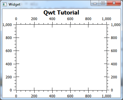
но край оси не совпадает с углами наружной оси, небольшое отклонение наступает. Я сделал скриншот здесь:
моя полная ничья
    void CustomScaleDraw::draw(QPainter *painter, const QPalette &palette) const
    {


        QwtScaleDraw::draw(painter, palette);


        painter->save();

        QPen pen = painter->pen();
        pen.setColor(palette.color(QPalette::Foreground));
        painter->setPen(pen);

        int majLen = m_pPlotWidget->majorTickLength();
        if (m_majTickStyle >= Both && majLen > 0){
            QList<double> ticks = this->scaleDiv().ticks(QwtScaleDiv::MajorTick);
            for (int i = 0; i < (int)ticks.count(); i++){
                const double v = ticks[i];
                if (this->scaleDiv().contains(v))
                    drawInwardTick(painter, v, majLen);
            }
        }
    }


and
void CustomScaleDraw::drawInwardTick(QPainter *painter, double value, int len) const
{


    int pw2 = qMin((int)painter->pen().width(), len) / 2;

    QwtScaleMap scaleMap = this->scaleMap();

    QPointF pos = this->pos();

    int majLen = tickLength(QwtScaleDiv::MajorTick);


    const int clw = m_pPlotWidget->lineWidth();
    const int tval = scaleMap.transform(value);

    bool draw = false;
    if ( orientation() == Qt::Vertical ){
        int low = (int)scaleMap.p2() + majLen;
        int high = (int)scaleMap.p1() - majLen;
        if ((tval > low && tval < high) ||
            (tval > high && !m_pPlotWidget->axisEnabled (QwtPlot::xBottom) && !clw) ||
            (tval < low && !m_pPlotWidget->axisEnabled(QwtPlot::xTop) && !clw)) draw = true;
    } else {
        int low = (int)scaleMap.p1() + majLen;
        int high = (int)scaleMap.p2() - majLen;
        if ((tval > low && tval < high) ||
            (tval > high && !m_pPlotWidget->axisEnabled(QwtPlot::yRight) && !clw) ||
            (tval < low && !m_pPlotWidget->axisEnabled(QwtPlot::yLeft) && !clw)) draw = true;
    }

    if (draw){

        switch(alignment()){

            case LeftScale:
            {
                QwtPainter::drawLine(painter, pos.x() + pw2, tval, pos.x() + len, tval);

                break;
            }
            case RightScale:
            {
                QwtPainter::drawLine(painter, pos.x() - pw2, tval, pos.x() - len, tval);
                break;
            }
            case BottomScale:
            {
                QwtPainter::drawLine(painter, tval, pos.y() - pw2, tval, pos.y() - len);
                break;
            }
            case TopScale:
            {
                QwtPainter::drawLine(painter, tval, pos.y() + pw2, tval, pos.y() + len);
                break;
            }
        }
    }
//    QwtPainter::setMetricsMap(metricsMap); // restore metrics map
}
моя настройка масштаба в QwtPlot.cpp
для (int i = 0; i m_minTickLength = 5;
m_majTickLength = 9; if(scale)
{
scale->setMargin(0);
//the axis title color must be initialized...
QwtText title = scale->title();
title.setColor(Qt::black);
scale->setTitle(title);
//...same for axis color
QPalette pal = scale->palette();
pal.setColor(QPalette::Foreground, QColor(Qt::black));
scale->setPalette(pal);
CustomScaleDraw *sd = new CustomScaleDraw(this);
sd->setTickLength(QwtScaleDiv::MinorTick, m_minTickLength);
sd->setTickLength(QwtScaleDiv::MediumTick, m_minTickLength);
sd->setTickLength(QwtScaleDiv::MajorTick, m_majTickLength);
setAxisScaleDraw(i,sd);
}
}
plotLayout()->setAlignCanvasToScales( true );
1 ответ
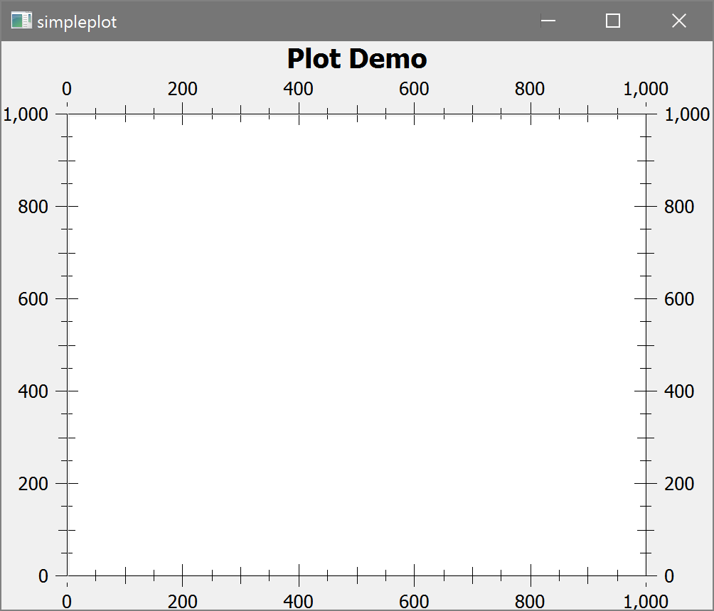
Вы можете добиться эффекта тиков, направленных внутрь, добавив на график дополнительные элементы масштаба, которые имеют свойство выравнивания, противоположное тому, которое обычно требуется для их положения.
Это требует гораздо меньше кода, чем пользовательский художник, и у вас нет проблем с выравниванием.
Выход
Код
#include <qapplication.h>
#include <qwt_plot.h>
#include <qwt_plot_curve.h>
#include <qwt_plot_grid.h>
#include <qwt_plot_layout.h>
#include <qwt_symbol.h>
#include <qwt_legend.h>
#include <qwt_scale_widget.h>
#include <qwt_plot_scaleitem.h>

int main( int argc, char **argv )
{
    // Enable high-DPI scaling with Qt 5.6+
#if (QT_VERSION >= QT_VERSION_CHECK(5,6,0))
    QApplication::setAttribute(Qt::AA_EnableHighDpiScaling);
#endif

    QApplication a( argc, argv );

    QwtPlot plot;
    plot.setTitle( "Plot Demo" );
    plot.canvas()->setContentsMargins(0, 0, 0, 0);
    plot.setStyleSheet("QwtPlot{ border: 0; }");
    plot.canvas()->setStyleSheet("QwtPlotCanvas {border: none; margin: 1; background-color: white;}");
    plot.plotLayout()->setCanvasMargin(0);

    plot.enableAxis(QwtPlot::yLeft);
    plot.enableAxis(QwtPlot::yRight);
    plot.enableAxis(QwtPlot::xBottom);
    plot.enableAxis(QwtPlot::xTop);

    plot.setAxisScale( QwtPlot::yLeft, 0.0, 1000.0 );
    plot.setAxisScale(QwtPlot::yRight, 0.0, 1000.0);
    plot.setAxisScale(QwtPlot::xBottom, 0.0, 1000.0);
    plot.setAxisScale(QwtPlot::xTop, 0.0, 1000.0);

    plot.axisWidget(QwtPlot::yLeft)->setMargin(0);
    plot.axisWidget(QwtPlot::yLeft)->setSpacing(0);
    plot.axisWidget(QwtPlot::yRight)->setMargin(0);
    plot.axisWidget(QwtPlot::xBottom)->setMargin(0);
    plot.axisWidget(QwtPlot::xTop)->setMargin(0);

    // create inward pointing ticks, and disable their labels
    // notice the alignment is *opposite* to the position.
    // in production code, don't hardcode the positions obviously.
    QwtPlotScaleItem *yLeftScaleItem = new QwtPlotScaleItem(QwtScaleDraw::RightScale, 0);
    yLeftScaleItem->scaleDraw()->enableComponent(QwtAbstractScaleDraw::Labels, false);
    yLeftScaleItem->attach(&plot);

    QwtPlotScaleItem *yRightScaleItem = new QwtPlotScaleItem(QwtScaleDraw::LeftScale, 1000);
    yRightScaleItem->scaleDraw()->enableComponent(QwtAbstractScaleDraw::Labels, false);
    yRightScaleItem->attach(&plot);

    QwtPlotScaleItem *xBottomScaleItem = new QwtPlotScaleItem(QwtScaleDraw::TopScale, 0);
    xBottomScaleItem->scaleDraw()->enableComponent(QwtAbstractScaleDraw::Labels, false);
    xBottomScaleItem->attach(&plot);

    QwtPlotScaleItem *xTopScaleItem = new QwtPlotScaleItem(QwtScaleDraw::BottomScale, 1000);
    xTopScaleItem->scaleDraw()->enableComponent(QwtAbstractScaleDraw::Labels, false);
    xTopScaleItem->attach(&plot);

    plot.updateCanvasMargins();

    plot.resize( 500, 400 );
    plot.show();

    return a.exec();
}

