CDC USB на dspic33EP
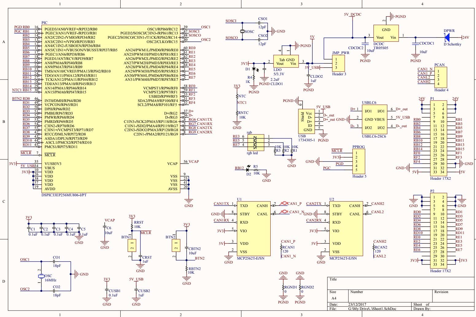
Я пытаюсь заставить свою фотографию общаться через USB с моим ПК (MacBook Pro). Вот схема для моей самодельной платы, использующей dsPIC33EP256MU806:  Я адаптировал библиотеку MLA для микрочипа, в частности, прошивку cdc_basic. Ниже приведены изменения, которые я внес в код:
- Изменил ACLKCON3 на 0x24C3, так как я использую кварцевый генератор 16 МГц.
- Убран весь код относительно кнопок и светодиодов.
- Код не компилировался, поэтому мне пришлось добавить #include.
Вот мои конфигурации прагмы:
// FGS
#pragma config GWRP = OFF // General Segment Write-Protect bit (General Segment may be written)
#pragma config GSS = OFF // General Segment Code-Protect bit (General Segment Code protect is disabled)
#pragma config GSSK = OFF // General Segment Key bits (General Segment Write Protection and Code Protection is Disabled)

// FOSCSEL
#pragma config FNOSC = FRC // Initial Oscillator Source Selection bits (Internal Fast RC (FRC))
#pragma config IESO = OFF // Two-speed Oscillator Start-up Enable bit (Start up with user-selected oscillator source)

// FOSC
#pragma config POSCMD = HS // Primary Oscillator Mode Select bits (XT Crystal Oscillator Mode)
#pragma config OSCIOFNC = OFF // OSC2 Pin Function bit (OSC2 is clock output)
#pragma config IOL1WAY = OFF // Peripheral pin select configuration (Allow multiple reconfigurations)
#pragma config FCKSM = CSECMD // Clock Switching Mode bits (Clock switching is enabled,Fail-safe Clock Monitor is disabled)

// FWDT
#pragma config WDTPOST = PS32768 // Watchdog Timer Postscaler bits (1:32,768)
#pragma config WDTPRE = PR128 // Watchdog Timer Prescaler bit (1:128)
#pragma config PLLKEN = ON // PLL Lock Wait Enable bit (Clock switch to PLL source will wait until the PLL lock signal is valid.)
#pragma config WINDIS = OFF // Watchdog Timer Window Enable bit (Watchdog Timer in Non-Window mode)
#pragma config FWDTEN = ON // Watchdog Timer Enable bit (Watchdog timer always enabled)

// FPOR
#pragma config FPWRT = PWR128 // Power-on Reset Timer Value Select bits (128ms)
#pragma config BOREN = ON // Brown-out Reset (BOR) Detection Enable bit (BOR is enabled)
#pragma config ALTI2C1 = OFF // Alternate I2C pins for I2C1 (SDA1/SCK1 pins are selected as the I/O pins for I2C1)

// FICD
#pragma config ICS = NONE // ICD Communication Channel Select bits (Reserved, do not use)
#pragma config RSTPRI = PF // Reset Target Vector Select bit (Device will obtain reset instruction from Primary flash)
#pragma config JTAGEN = OFF // JTAG Enable bit (JTAG is disabled)

// FAS
#pragma config AWRP = OFF // Auxiliary Segment Write-protect bit (Aux Flash may be written)
#pragma config APL = OFF // Auxiliary Segment Code-protect bit (Aux Flash Code protect is disabled)
#pragma config APLK = OFF // Auxiliary Segment Key bits (Aux Flash Write Protection and Code Protection is Disabled)
Вот мой основной цикл:
int main(void)
{

    SYSTEM_Initialize(SYSTEM_STATE_USB_START);

    USBDeviceInit();
    USBDeviceAttach();

    LATEbits.LATE5=1;

    while(1)
    {
        SYSTEM_Tasks();

        #if defined(USB_POLLING)
            // Interrupt or polling method. If using polling, must call
            // this function periodically. This function will take care
            // of processing and responding to SETUP transactions
            // (such as during the enumeration process when you first
            // plug in). USB hosts require that USB devices should accept
            // and process SETUP packets in a timely fashion. Therefore,
            // when using polling, this function should be called
            // regularly (such as once every 1.8ms or faster** [see
            // inline code comments in usb_device.c for explanation when
            // "or faster" applies]) In most cases, the USBDeviceTasks()
            // function does not take very long to execute (ex: <100
            // instruction cycles) before it returns.
            USBDeviceTasks();
        #endif

        //Application specific tasks
        APP_DeviceCDCBasicDemoTasks();

    }//end while
}//end main
Остальная часть кода находится здесь: https://github.com/RuiLoureiro/CDC_USB_dsPIC33e256MU806
Когда я перечисляю устройства USB, подключенные в данный момент к моему macbook, используя ls /dev/tty.*, изображение не отображается. Любая помощь будет оценена.